ShareThis Widget

29 April 2011

Solid Waste Disposal: planning requirements & equipment


PAUL HAY Capital Projects


Solid Waste Disposal

Author:          Paul Hay
e-mail:             paul.hay@phcjam.com
profile:            www.linkedin.com/in/phcjam


1.0         SOLID WASTE DISPOSAL USES ENERGY AND SPACE

1.1            Energy is first used to package and transport goods then to collect them as trash.

1.2       Trash compactors also have energy and space requirements.

1.3       Provision for the delivery of supplies, collection and storage of solid waste can (a) require more space than other disposal systems; (b) present a fire hazard; and (c) can create serious local environmental problems.

1.4       Solid Waste is considered as either Ahigh grade@ or Alow grade@ resources: the former being recyclable and the latter fuel for incineration.
1.4.1    High grade resources include aluminum, steel, paper, cardboard and some plastics;
1.4.2    Incineration of low grade resources may cause air pollution and ash-disposal problems.
1.4.3    Low grade resources should be kept clean and dry before burning.

1.5       The earlier resources are separated the less energy will be used.

1.6       Recycling saves energy.
1.6.1    50% less energy is used to produce cardboard from recycled material;
1.6.2    52% less to recycle steel; and
1.6.3    96% less to recycle aluminum.

1.7       Anaerobic combustion in enclosed land-fills will generate methane gas after many years, and this can be used to support generation of electricity and co-generation: where heat is recovered from the generating process.


2.0         DISPOSAL OF RESIDENTIAL WASTE SHOULD BE PLANNED

2.1       Solid waste should be stored in well ventilated spaces.

2.2       The Kitchen is generally the location for storage of solid waste in residences.

2.3       A better location for storage of residential waste is in a room entered from the Kitchen and opening to the outdoors.

2.4       Garbage disposal units grind organic food scraps and dispose of them into the central sewer where they are better able to bio-degrade than in landfills.
2.4.1    Water and energy are used in the process.
2.4.2    The central sewers also require more energy to treat the increased flow.
2.4.3    Moisture is reduced in garbage receptacles which keeps waste in a better condition for incineration; and
2.4.4    Weight of garbage is reduced in the process.

2.5       Garbage compactors are not necessarily advantageous.


3.0       DISPOSAL OF WASTE NEEDS TO BE FACILITATED IN LARGE BUILDINGS

3.1       Industrial and commercial processes generate waste of all types: some being toxic.

3.2       Collection of waste is a three stage process.
3.2.1    Waste generated at work stations are initially placed in bins provided.
3.2.2    Bins are emptied into collection carts which are stored in service closets until full;
3.2.3    These closets have service sinks to wash the bins; and
3.2.4    In the final stage, trash is transported to the ground floor via service elevator for further storage and processing.

3.3       Storage spaces need to be cool, dry and well ventilated.
3.3.1    Burnable trash can be shredded and incinerated.
3.3.2    A sprinkler system is advisable; but
3.3.3    Regulations may limit use of incinerators.

3.4       The garbage is finally collected and transported away from the building.


Figure showing Stages for Collection of Waste

Fig. 1: Stages for Collection of Waste [Source:- Mechanical & Electrical Equipment for Buildings]


4.0         SPECIALIZED EQUIPMENT MAY BE USED


4.1       Incineration reduces waste transported to landfill.

4.2       Modern incinerators produce less pollution and facilitates heat recovery.
4.2.1    Hot water or steam is produced.
4.2.2    In large-scale operations, steam produced can be used to generate electricity.  
  
4.3       Garbage can be compacted and bagged.

4.4       Compactors can reduce the volume of trash by 90%.
4.4.1    Compactors need to be vibration-isolated.
4.4.2    Some compactors are manually free standing and others automatic chute-fed.
4.4.3    Many have built-in sprays for fire control and disinfection.
4.4.4    Access to water and floor drains is desirable.

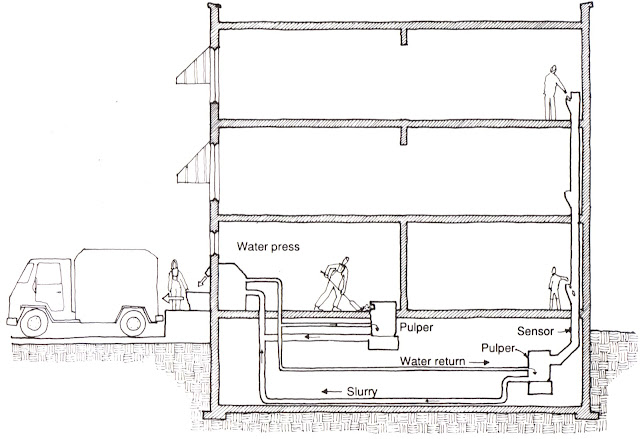
4.5       Pulping systems (a) reduce air pollution that may result from use of incinerators, and (b) reduce space needed for storage.
4.5.1    Water is introduced and waste ground into pulp.
4.5.2    90% of water is extracted by a water press to leave a transportable slurry.
4.5.3    The volume of waste is reduced by 20%.
4.5.4    Extracted water is re-used.
4.5.5    Pulping systems should not be used for metals or plastics.

4.6       Vacuum systems use a grinder and evacuation tube.
4.6.1    Air is used as the medium for transportation.
4.6.2    Lines are small and waste can be moved horizontally or upwards.

Figure showing Pulping System

Fig. 2:  Pulping System [Source:- Mechanical & Electrical Equipment for Buildings]


FURTHER READING

            Mechanical and Electrical Equipment for Buildings, 8th edition, Benjamin Stein, John S. Reynolds, John Wiley & Sons Inc., USA, 1992

Conveyance Systems: escalators, elevators, etc.


PAUL HAY Capital Projects


Conveyance Systems

Author:          Paul Hay
e-mail:            paul.hay@phcjam.com
profile:           www.linkedin.com/in/phcjam


1.0   MECHANICAL DEVICES MOVE PEOPLE & FREIGHT

1.1_      Moving Walks and ramps are used to (a) assist in walking long distances, (b) transport large and bulky objects, and (c) reduce congestion:
1.1.1   Inclines up to 15E can be provided;
1.1.2   Maximum allowable speeds depend on the inclination and design approaches.

1.2       Pneumatic tubes transport cylinders containing paperwork, money, etc. from one end of a tube to another:
1.2.1   Sizes range from 50 mm diameter to 150 mm x 450 mm (for x-rays);
1.2.2   Air pressure propels the cylinders through the tubes; and
1.2.3   Complex systems use computers to deliver cylinders to pre-selected locations along the tube.

1.3       Endless belt conveyors carry paperwork horizontally in packs or vertically in slots.


Conveyor System


Figure 1: Conveyor System

[Source:- AIA Architectural Graphics Standards]


1.4       Trays and dumbwaiters carry paperwork, food, etc. between departments in large commercial buildings or between floors of multi-storey buildings:
            1.4.1   Tray systems automatically transport trays via moving carriers between dispatch cut-outs at intervals along a chain;
1.4.2   Dumbwaiters use ropes and pulleys to transport items on cars or platforms through a vertical shaft:
1.4.2.1            They can be manual or automatic;
1.4.2.2            Manual operation is limited to two floors;
1.4.2.3            They are used in restaurants, libraries, and offices;
1.4.2.4            Vertical shafts should be installed adjacent to other vertical shafts.

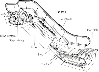
1.5       An escalator is a mechanical staircase with moving treads which transport standing pedestrians.

1.6       Elevators can be electric traction or hydraulic.

2.0   ESCALATORS ARE MORE EFFICIENT THAN ELEVATORS

Escalator

Fig. 2: Escalator

[Source:- Mechanical & Electrical Equipment for Buildings]


2.1       Escalators occupy a fifth of the space elevators require to transport comparable amounts of people.

2.2       A sixth less escalators are required to move comparable amounts of people.

2.3       Escalators are typically 800 mm or 1,000 mm wide between handrails.

Escalator in crisscross arrangement


Figure 3: Escalator in crisscross arrangement

[Source:- Mechanical & Electrical Equipment in Buildings]

2.4       They are usually installed in pairs:
2.4.1   They can be installed in parallel or criss-cross;
2.4.2   Treads and handrails are inclined at 30E from the lower floor;
2.4.3   50 m2 space should be provided at either end of the escalator to facilitate easy mounting and dismounting.


Escalator in parallel arrangement


Figure 4: Escalator in parallel arrangement

[Source:- Mechanical & Electrical Equipment in Buildings]

2.5       Escalators can serve up to 5 storeys.

2.6       Escalators are constructed as a steel-trussed framework:
2.6.1   Motor-driven sprocket wheels at each end revolve to form two chains which pull a conveyor-belt of treads;
2.6.2   Sprocket wheels and chains also move the handrails;
2.6.3   Automatic roller shutters can be deployed over tops of horizontal wellway openings for fire protection on any floor:
2.6.3.1            Sprinklers can be installed on the soffit of the escalators and on the ceiling immediately surrounding the wellway;
2.6.3.2            Blowers on the roof can force fresh air through floor openings; and
2.6.3.3Extractors can exhaust indoor air above the roof.


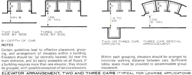
3.0         DESIGN FOR ELEVATORS INVOLVE THEIR LOBBIES AND CABS

Elevator Lobbies


Figure 5: Elevator Lobbies

[Source:- AIA Architectural Graphics Standards]

3.1       Double-decker cabs require escalators to transport people from the ground floor to the upper floor.

3.2       Sky lobbies require the building to be divided into 2 or 3 zones:
3.2.1   Each zone has independent elevator systems using a common shaft;
3.2.2   Express elevators facilitate movement between lobby zones.

3.3       Clear opening for commercial installations is typically 1,050 mm.

3.4       Clear opening up to 1,500 mm wide are available for service elevators and hospitals.

3.5       Centre-opening doors provide the fastest closing speeds.

3.6       Emergency power is recommended as brakes hold cabs stationery during power outages or brown-outs:
3.6.1   Hydraulic elevators and small traction cabs can be lowered manually; but
3.6.2   Emergency power is critical for large cabs, especially express elevators.


Traction & Hydraulic Elevators


Figure 6: Traction & Hydraulic Elevators

[Source:- AIA Architectural Graphic Standards]


4.0   TRACTION ELEVATORS ARE MORE ECONOMICAL TO OPERATE

4.1       Mechanical components include (a) grooved sheave, (b) electric motor with brakes, (c) auxiliary equipment, (d) elevator shaft, (e) guide rails, (f) cab, (g) hoist wire ropes, (h) counter-weight, and (i) safety springs or buffers.

4.2       The sheave, motor and auxiliary equipment are located in a machine room:
4.2.1   The machine room is typically located over the shaft but the motor can be located in the basement; but
4.2.2   Basement location increases power consumption, loading on overhead supports, and wear on ropes;
4.2.3   The room is approximately twice the size of the shaft;
            4.2.4   1 2 additional storeys is required above the top of the beam supporting the elevator shaft.

4.3       Guide rails, cabs, counter-weight, and spring/buffers are installed in the shaft:
4.3.1   Guide rails are placed on each side of the cab;
4.3.2   The hoist wire is attached to the top of the cab at one end, wraps around the sheave, and is attached to the counter-weight at the other end.


5.0        HYDRAULIC ELEVATORS ARE INSTALLED IN LOW-RISE BUILDINGS

5.1       Buildings are typically no higher than 18 m.

5.2       Mechanical components include (a) reservoir, (b) pump, (c) elevator shaft, (d) guide-rails, (e) cab, (f) plunger, and (g) safety springs or buffers.

5.3       The cab is supported by the plunger within the elevator shaft.

5.4       Oil from a reservoir is pumped into the plunger to raise the cab.

5.5       Oil is released from the plunger to lower the cab.

5.6       Plunger may require a hole below the basement floor to a depth equivalent to the travel of the elevator.


FURTHER READING

Mechanical and Electrical Equipment for Buildings, 8th edition, Benjamin Stein, John S. Reynolds, John Wiley & Sons Inc., USA, 1992
Construction Materials & Processes, Don G. Watson, McGrawHill Book Co., USA, 1978;
Architectural Handbook, Alfred M. Kemper, John Wiley & Sons Inc., USA, 1979