ShareThis Widget

30 June 2011

Principles of Lighting: Visible Light, Perception, Light source, & Illumination


PAUL HAY Capital Projects


Principles of Lighting

Author: Paul Hay
e-mail:   paul.hay@phcjam.com


1.0     INTRODUCTION TO LIGHT


1.1               1.1              Light is an electro-magnetic wave.

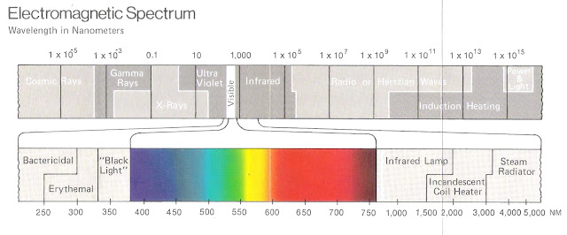
Figure showing Visible light as a portion of the Electromagnetic Spectrum

Figure 1: Visible light as a portion of the Electromagnetic Spectrum. Source: Philips Lighting - Lighting Handbook


1.2       The electro-magnetic spectrum for light has wave-lengths in the range 0.2 – 1,000 µm:
1.2.1    Solar radiation has a spectrum with wave-lengths in the range 0.3 – 25 µm; and
1.2.2 Visible light has a spectrum with wave-lengths in the range 0.38 – 0.78 µm.
Figure showing how sensitivity of the human eye to colours varies

Figure 2: Sensitivity of the human eye to colours varies.  Source:- Philips Lighting - Lighting Handbook


1.3       Objects are perceived from a complex pattern of light, shade and contours.

1.4       Light from at least two directions, preferably at an acute angle to each other, provides the best modeling characteristics for display of three dimensional objects.
Figure showing how (a) Diffuse lighting destroys textures, but (b) necessary modeling shadows are created when combined with directional lighting.

Figure 3: (a) Diffuse lighting destroys textures, but (b) necessary modeling shadows are created when combined with directional lighting.  Source:- Mechanical & Electrical Equipment for Buildings


1.5       The ability of the human eye to distinguish details depends on (a) the size of the object being viewed, (b) contrast of the object with its immediate surroundings, and (c) the level of illumination present.


2.0      CHARACTERISTICS OF LIGHTING SOURCES

2.1       Luminous Flux is the radiant energy which produces a luminous sensation [i.e. lumens].

2.2       Luminous Efficacy is the ratio of total luminous flux emitted by a light source to the total power input [i.e. Lumens/Watt]:
            2.2.1    The Luminous Efficacy of daylight varies between 100 – 120 lumens/Watt; and
            2.2.2   Current electric-lighting systems attain efficacies between 60 -90 Lumens/Watt.

3.0      PRINCIPLES OF ILLUMINATION

3.1.      Wave intensity [I] is the power of radiant flux incident on a unit area of a reference plane perpendicular to the direction of propagation [i.e. W/m2].

3.2       Illumination is the density of luminous flux incident on a unit area of a reference plane [i.e. lux]:
            3.2.1.   The Inverse-square Law states that wave intensity [I] from a point source in free space is inversely proportional to the square of the distance (d) from the source:

                        I α 1/d 2                                                                                                           3.1

            3.2.2. The Cosine Law states that radiant flux [F] on any surface varies as the cosine of the angle of incidence (q) of the wave to the normal of the surface:

                        F α Cos q                                                                                                        3.2

3.3       Luminous flux from the sky gives relatively constant illumination, but varies according to the portion of sky which is incident on the surface being evaluated:
            3.3.1.   In the arid tropics, skies are typically isotropic: luminous flux is evenly distributed about the sky, but bright areas exist at (a) the point which mirrors the location of the sun, and (b) the horizon, which is called circumsolar radiation;
            3.3.2.  In the humid tropics, skies are anisotropic: the brightest areas being associated with the location of clouds in the sky.

3.4       Radiant exchange between the sky and a small surface near ground can be modeled by representing the sky as a hemisphere.

3.5       Efficient interior lighting depends on (a) available luminous flux, (b) its distribution, (c) glazing/controller properties and (d) room characteristics. 


27 June 2011

Daylighting: benefits, illumination, & solar control


PAUL HAY Capital Projects


Daylighting: Benefits, Illumination & Solar Control

Author:          Paul Hay
e-mail:            paul.hay@phcjam.com
profile:           www.linkedin.com/in/phcjam


1.0  BENEFITS OF DAYLIGHTING

1.1        Total energy-use in buildings can be reduced by up to 20% in climates like Jamaica's.
1.1.1     Use of electric lights can be reduced by 65%; and
1.1.2     Peak cooling-load can be reduced by 15%.

1.2        The value of buildings are increased; and

1.3        Productivity of occupants is increased.

2.0  PROVIDE ADEQUATE ILLUMINATION

2.1        Illumination required within a room depends on the use of the space.

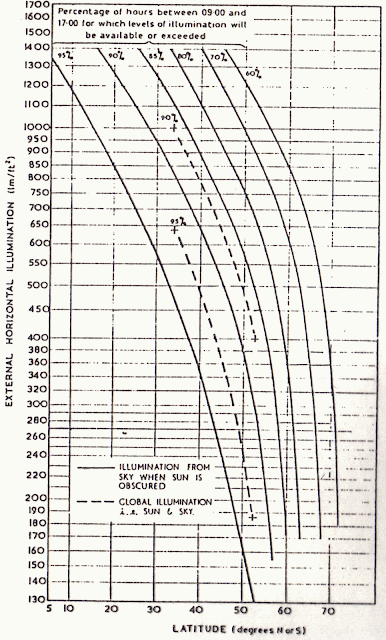
2.2        Partly cloudy skies are typical of tropical climates and available illumination is generally higher than in locations of higher latitude.

2.3.       Daylight Factors [DF] are used instead of absolute values of illumina­tion, because daylight is by nature variable;
2.3.1     Daylight Factor is the quotient of indoor illumination [Ein] at a specific point to the outdoor illumination [Eout] measured under an unobstructed sky.

DF =    Ein/Eout x 100 (%)                                                                                        [2.1]

2.3.2     Direct sunlight is generally excluded from the measure­ment of both indoor and outdoor illumination.

2.4        A scale model is required to study the illumination and quality of lighting.
2.4.1     For medium to large enclosures, a scale of 1:25 is recommended.
2.4.2     For small spaces with ceiling heights up to 3 m, a scale of 1:10 is recommended.
2.4.3     The scale of the model should be doubled for qualitative studies, to permit greater attention to construction details and allow sufficient distances for eyes or camera.


Figure showing available daylight Illumination at various Latitudes
Fig. 1:

Available Daylight Illumination at various Latitudes


3.0       AVOID THERMAL DISCOMFORT

3.1        Relatively uniform distribution of daylight factors is recommended:
3.1.1     With side-lighting, illumination near windows are typically 200% higher than illumination to the back of a room; and
3.1.2     With sky-lights, illumination beneath the sky-light may only be 50% higher than the lowest illumination away from the sky-light.

3.2        Increasing window-areas increases solar heat-gains, so window performance should be evaluated by use of the Effective Apertures of each window examined:


Fifure showing potential cost savings on cooling system with use of daylighting
Fig. 2: Potential Cost Savings on Cooling System with use of daylighting

Table showing Illumination levels for activity/area
Table 1: Illumination levels for activity/area
          
3.2.1     Effective Aperture [EA] is a lumped parameter derived from the window-to-wall ratio of the glazing in ceiling-high walls, or the Skylight-to-roof ratio;           

EA =     WWR x Tv                                                                                      [3.1]

or,        EA =     SSR x Tv x WF                                                                               [3.2]

                        where,
WWR   = Window-to-Wall Ratio [0<WWR<1]
SRR      =  Skylight-to-Roof Ration [0<SRR<1]
Tv         =  Visible transmittance of the glazing
WF       =  Light-well transmission

3.2.2     The ratio of net visible transmittance to Shading Coeffi­cient (i.e. Tv/SC) is typically (a) 0.67 for grey or bronze-tinted glazing, (b) 1.0 for skylight glazing (not considering light-well transmittance), and (c) 1.1 for blue-green glass.

3.3        Daylight Satura­tion is the point at which there is no further reduc­tion in electric-lighting:
3.3.1     For sidelighting, daylight saturation occurs at effective apertures of 0.10 and 0.25,
3.3.2     For sky-lighting, daylight saturation occurs at 0.02 to 0.03.

3.4        If win­dow areas are increased after daylight satura­tion occurs, then solar heat-gains, cooling loads, and overall energy-consump­tion will be increased.

4.0       INTEGRATE ELECTRIC LIGHTING

4.1        Lighting zones must be developed based on contrast levels of daylight illumination:
4.1.1     Lighting zones delineate spaces having similar daylight distribution characteris­tics, but not the nature of lighting required.
4.1.2     Contrast level for a zone is the ratio of maximum to minimum illumination within the zone; and
4.1.3     Three zones are recommended with contrast levels of 1:3, 1:6 and 1:9 respec­tively.
4.1.4     For high windows with a 3 m high ceiling, two daylit zones can assumed by the 15/30 rule-of-thumb:
4.1.4.1  The first 4.6 m [15-ft] in from the windows is predominantly daylit;
4.1.4.2  The next which ends 9.1 m [30-ft] in from the windows is ambient-lit by daylight and is supplemented by electric-lighting.

4.2        The nature of lighting may vary within a zone and a zone can be established outside of daylighting concerns.
4.2.1     General lighting is the illumination generally required throughout an area;


4.2.2     Background lighting is the illumination within the visual field against which an object is seen; and
4.2.3     Task lighting is illumination specifically for visually-demanding activities.   
          
4.3        Appropriate controls must be provided for electric-lights.

4.4        Electric-light should have colour and direction similar to daylight.


FURTHER READING

Daylighting in Architecture, Benjamin H. Evans, Architectural Record Books, New York, 1981;
Concepts and Practice of Architectural Daylighting Fuller Moore, Van Nostrand Reinhold, New York, 1985;

08 June 2011

Building Energy Transfers: Modes of Heat Transfer, Thermo-physical Properties of Materials, and Calculation of U-value


PAUL HAY Capital Projects


Building Energy Transfers & Properties of Materials

Author:          Paul Hay
e-mail:            paul.hay@phcjam.com
profile:           www.linkedin.com/in/phcjam


1.0       INTRODUCTION TO ENERGY TRANSFERS & MODES OF TRANSFER           

1.1       Majority of heat transfer in the tropics is through thermal radiation.

1.2       Heat transfer can be either "Steady State" or "Periodic" in nature.

1.3       Energy transfers primarily depend on (a) difference of the ambient air-temperature to the indoor air temperature, (b) thermo-physical properties of the construction materials, and (c) location of materials in the assembly of the building component.


2.0       PERIODIC HEAT TRANSFER

2.1       Periodic (or Non-Steady-State) Heat Transfer is the thermal condition in which temperature on at least one side of a material and distribution within the material fluctuate predictably.

2.2       Thermal Mass is the measure of a building component's ability to absorb heat while undergoing a temperature change.

2.3       (Volumetric) Heat Capacity is the measure of a material's ability to store or absorb heat while undergoing a temperature change.


3.0       STEADY-STATE HEAT TRANSFER

3.1       Steady-State Heat Transfer is the thermal condition in which temperature on each surface of a material and distribution within the material is uniform and constant with time.
           3.1.1    Surface Coefficients are thermo-physical properties of surfaces that assume the existence of steady-state heat transfer; and
           3.1.2    Thermal Conductance is another thermo-physical property of a material that assumes the existence of steady-state heat transfer.

3.2       Rate of Heat Transfer (Q) through a building component is dependent on the temperature difference across its outermost surfaces, ventilation loss, its area and Overall Thermal Transmission Coefficient (i.e. U-value):
           3.2.1    Overall Thermal Transmission Coefficient (U) is the overall (i.e. area-weighed) coefficient of heat transfer from air to air arising from conduction through a building component (eg. roof) [unit = W/m2.K];
          3.2.2    The U-value depends on (a) the individual thermal conductance of its components and (b) the placement of components relative to each other;
          3.2.3    The Jamaican Energy Efficiency Building Code [EEBC-94] stipulates a maximum U-value for specific climatic zones in Jamaica.


4.0   THERMO-PHYSICAL PROPERTIES OF MATERIALS

4.1       Thermal Conductivity (k) is the rate of heat flow through a unit area and unit thickness of an homogeneous material, under steady-state conditions, for a unit temperature gradient perpendicular to the area [unit = W/m-K].

4.2       Thermal Conductance (C) is the rate of heat flow through a unit area of a component from one of its bounding surfaces to the other for a unit temperature difference between the two surfaces, under steady state conditions [unit = W/m2-K]

4.3       Individual thermal conductance can be derived from the thickness of the component (t) and its conductivity (k) as follows:
            C = k/t                                                                                                  [4.1]

4.4       Thermal Resistivity (r) is the reciprocal of the thermal conductivity [unit = m.K/W]:
             r = 1/k                                                                                                  [4.2]
It indicates the thermo-physical property of a material as a thermal insulator.

4.5       Thermal Resistance (R) is the reciprocal of thermal conductance [unit = m2.K/W]:
            R = 1/C = t/k                                                                                         [4.3]

            It indicates the thermo-physical property of a component as a thermal insulator.


5.0       CALCULATION OF U-VALUE


Example:-  Calculate Ur for a roof constructed as per sketch


ho =     22.7 W/m2-K
hi =      6.14 W/m2-K
a. Subscript numbers conform to  identification of components.

Conductances at joists are as followsa:
C2 =     17.0 W/m2-K
C3 =     4.09 W/m2-K
C4 =     7.32 W/m2-K
C7 =     12.5 W/m2-K
C8 =     4.54 W/m2-K

Also,
k6 =     0.12 W/m-K
Therefore,
b.  Actual thickness of 200 mm (nom.) deep joist is 184 mm or 0.184 m.

C6 =     k6/t =   0.12/0.184b =   0.63 W/m2-K
And,
1/Uj =  1/ho + 1/C2 + 1/C3  + 1/C4 + 1/C6 + 1/C7 + 1/C8 + 1/hi
     =     1/22.7 + 1/17 + 1/4.09 + 1/7.32 + 1/0.63 + 1/12.5 + 1/ 4.54 + 1/6.13
     =     2.53 m2-K/W
So,
Uj   = 1/2.53 =             0.40 W/m2-K

c.  Conductance of air-space assumes heat-flow is downward, mean temperature = 32 EC & temp. difference = 5 K
Conductance at air-space is as follows:
C5 =     5.68 W/m2-K

And,
1/Us =  1/ho + 1/C2 + 1/C3  + 1/C4 + 1/C5 + 1/C7 + 1/C8 + 1/hi
       =   1/22.7 + 1/17 + 1/4.09 + 1/7.32 + 1/5.68 + 1/12.5 + 1/4.54 + 1/6.13
       =   1.12 m2-K/W

So,
Us   =                           1/1.12 =           0.89 W/m2-K


And,
Ur =     (Uj Aj + UsAs)/(Aj + As)
     =     UjAj /(Aj + As) + UsAs /(Aj + As)
     =     0.40 x 0.10 + 0.89 x 0.90
     =     0.84 W/m2-K

06 June 2011

Fenestration: Window Size, Type of Glass & Shading Devices


PAUL HAY Capital Projects


Fenestration: Window Size, Type of Glass & Shading Devices


Author:          Paul Hay
e-mail:            paul.hay@phcjam.com
profile:           www.linkedin.com/in/phcjam


1.0   INTRODUCTION TO FENESTRATION


1.1_      Majority of heat transfer in the tropics is through thermal radiation.

1.2       Solar radiation incident on building apertures is in the form of (a) beam, (b) diffused (i.e. skylight) and reflected radiation.

1.3       Visible light is a component of solar radiation; and


Illustration of Visible Light as a portion of Electromagnetic Spectrum

Fig. 1 - Visible Light as a portion of Electromagnetic Spectrum


1.4       The National Building Code of 1983 requires habitable rooms to have one or more windows or skylights, not otherwise provided with light and ventilation.

2.0    SIZE OF APERTURES

2.1       The Building Code further requires the combined area of a room's skylights and windows to be no less than 10% of its floor area, at least half of which should be operable to facilitate ventilation.

2.2       Apertures should be uniformly distributed throughout a room for good daylighting:
2.2.1   Skylights provide more uniform lighting than windows;
2.2.2   Locating windows as high as possible within a room improves distribution.

2.3       A survey taken in Britain to determine the size of windows for adequate view determined that building occupants had no preference for window height but required that window width be at least one-third the width of their adjacent wall.

2.4       In the humid tropics, solar heat-gain [SHG] increases as apertures get larger, even if natural lighting is used to supplement electric lighting.
      

3.0   TYPICAL GLAZING CHARACTERISTICS

3.1       The transmission, absorption and reflection of solar radiation by glass depends on (a) the angle of the beam; as well as the (b) thickness, (c) refractive index, and (d) absorption/extinction coefficient [K] of the glass.


Figure showing Glazing Characteristics of Clear Glass

Fig. 2 - Glazing Characteristics of Clear Glass


3.2       Fresnel studied the reflection of non-polarized radiation off smooth surfaces where the refractive index for material of the smooth surface was different from the medium through which the radiation passed (eg. air):
3.2.1   For clear 6 mm thick glass, reflectivity was consistently low for angles of incidence normal to the surface and up to 45E from the normal, then totally reflective as the incidence became parallel to the surface;
3.2.2   Beam radiation with a 60E angle of incidence is equivalent to the transmittance for an isotropic sky.


3.3    Solar heat-gain from glazing is the combination of transmitted solar radiation and up to 50% of absorbed radiation:

SHG   = Solar Transmission + Solar Absorption emitted and convected indoors [3.1]

3.3.1   Under typical conditions approximately 30% of solar absorption is emitted and convected indoors;
3.3.2   Glasses which have greater K absorb more solar radiation;
3.3.3   K in glasses vary from a low of 4 m-1 for glasses which appear white when viewed from the edge to a high of 32 m-1 for glasses which appear green when viewed from the edge.


4.0   SPECIAL GLAZING

4.1       Double glazing is not cost-effective in the humid tropics;

4.2       Solar Control Glasses are classified as (a) heat-absorbing, (b) heat-reflecting, (c) heat-reflecting polyester film over clear glass, or (d) photo-chromatic glasses.

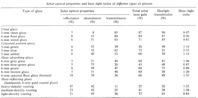
4.3     Glazing which transmits more heat than light should be avoided in the tropics.


Table showing Solar optical Properties and Heat-to-Light ratios of different Glasses

Table 1 - Solar optical Properties and Heat-to-Light ratios of different Glasses


5.0   SHADING   

5.1    Operable shading is more effective than fixed shading, if used to reduce glare and intense solar radiation;   

5.2       Shading is more efficient when located outdoors.   

5.3       Large overhangs reduce indoor lighting levels, though lighting levels are more uniform.

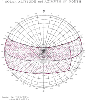
5.4       The size and configuration of shading devices should be determined with use of suncharts:


Figure showing Sunchart of Jamaica

Fig. 3 - Sunchart of Jamaica


5.4.1   Shading masks are two dimensional representations of shading available from a shading device or adjacent structures;


Sunchart of Jamaica with overlay showing need for (a) 50% & (b) 100% Shading

Fig. 4 - Sunchart of Jamaica with overlay showing need for (a) 50% & (b) 100% Shading


5.4.2   Shading devices can be categorized as (a) overhangs, (b) fins, (c) baffles, or (d)  combinations of two or more; and
5.4.3   Shading devices do not have to be monolithic.


Natural Ventilation: Windows, Walls & Other Devices


PAUL HAY Capital Projects

Topic:              Natural Ventilation: Windows, Walls & other influences
Author:            Paul Hay
e-mail:              paul.hay@phcjam.com
profile:             www.linkedin.com/in/phcjam


1.0       INTRODUCTION           


.1            Ventilation is the movement of air through a space, whether open or enclosed:
            1.1.1   Kinetic energy sustains ventilation through a building;
            1.1.2   Air pressure is directly proportional to the density of the air and the square of its velocity.
1.2       Natural Ventilation is the exchange of indoor air with fresh outdoor air by natural means:
            1.2.1   Temperature and pressure differences produce natural ventilation;
            1.2.2   Design of openings (i.e. windows, doors, vents, etc.) affects natural ventilation;
            1.2.3   Air exchange is necessary to maintain proper air quality;
            1.2.4   Mechanical systems should augment natural ventilation in the event of poor wind conditions.

2.0       ROOM OPENINGS

2.1       Where one opening exists, it serves as both inlet and outlet:
            2.1.1   When wind is perpendicular to the opening, natural ventilation will not be significantly influenced by increasing the size of the opening; but
            2.1.2   Ventilation will improve with larger openings when wind is oblique to the opening.
2.2       Natural ventilation is significantly improved with use of two openings if inlet and outlet sizes are increased equally.

TABLE 1:              RELATIVE AIR VELOCITIES IN NATURALLY VENTILATED ROOMS

WIND DIRECTION
OPENINGS
INTERIOR AIR SPEED

AMT
WIDTH
LOCATION
AVERAGE
MAXIMUM
Perpendicular
1
66%
Windward
13%
18%

1
100%
Windward
16%
20%
Oblique
1
66%
Windward
15%
33%

1
100%
Windward
23%
36%
Oblique
1
66%
Leeward
17%
44%

1
100%
Leeward
17%
39%
Oblique
2
66%
Leeward
22%
56%

2
100%
Leeward
23%
50%


2.3       Cross Ventilation is the flow of air from an inlet to an outlet not located on the same wall:
            2.3.1   Cross ventilation is best when inlets and outlets are the full width of the wall;
            2.3.2   Outlets are located on walls experiencing negative wind pressure;
            2.3.3   The vertical location of outlets relative to outlets influences ventilation:
                        2.3.3.1            Ventilation is best when inlets are low and outlets high, because the air current cools occupants and extracts warm air adjacent to ceilings;
                        2.3.3.2            Occupants are also cooled when both inlets and outlets are low, but warm air adjacent to ceiling is not extracted; nevertheless,
                        2.3.3.3            Warm air adjacent to ceiling is extracted when both inlets and outlets are high, but occupants are not cooled.

TABLE 2:              RELATIVE AIR VELOCITIES IN CROSS VENTILATED ROOMS

WIND DIRECTION
OPENINGS
INTERIOR AIR VELOCITY

AMT.
WIDTH
LOCATION
AVERAGE
MAXIMUM
Perpendicular to inlet
            2
            66%
Adjacent to windward inlets
45%
68%

            2
100%
Adjacent to windward inlets
51%
103%
Oblique to inlet
            2
            66%
Adjacent to windward inlets
37%
118%

            2
100%
Adjacent to windward inlets
40%
110%
Perpendicular to inlet
            2
            66%
Opposite to windward inlets
35%
65%

            2
100%
Opposite to windward inlets
37%
102%
Oblique to inlet
            2
            66%
Opposite to windward inlets
42%
83%

            2
100%
Opposite to windward inlets
42%
94%


3.0       OTHER INFLUENCES

3.1       Fins can improve natural ventilation:
            3.1.1   Fins increase ventilation through windward openings considerably; and
            3.1.2   Air flow can triple if wind is oblique to the opening.
3.2       The influence of internal partitioning cannot be readily generalized and should be determined by experimentation.