ShareThis Widget

31 August 2011

Water Supply: Pipe Size Calculation


PAUL HAY Capital Projects


Pipe Size Calculation

Author:          Paul Hay
e-mail:            paul.hay@phcjam.com
profile:           www.linkedin.com/in/phcjam


Problem:-  Find service pipe size given the following:

                       Street main pressure [E]               = 350 kPa
                       Height of uppermost fixture
                       (above street)                              = 10 m
                       Uppermost fixture                       = WC with flush valve
                       Total fixture units in the systema   = 85


a. See table 1 for supply fixture units of individual plumbing fixtures.


                       Developed length (DL) of piping (to
                       highest and most remote fixture)   = 30 m
                       Predominant flushing mechanism   = Flush valves


Table showing Water Supply Fixture-Unit Values

Table 1: Water Supply Fixture-Unit Values [source:- International Residential Code]


Solution:-  Calculation of Service Pipe Size


                       1.            Find the pressure required in the system to provide the minimum fixture pressure [A] for uppermost fixtureb:

b. see value for Aflush valve for closet in table 2


                     A         = 103 kPa


Table showing Minimum Pressure & Flow required for typical plumbing fixtures

Table 2:  Minimum Pressure & Flow required for typical plumbing fixtures   [source:- Mechanical & Electrical Equipment in Buildings]

                      2.            Calculate the Static Head [B]:

                   B         = 10 kPa/m x Height of uppermost fixture
                  = 10 x 10 m
                  = 100 kPa


Table showing Minimum pipe sizes for typical plumbing fixtures

Table 3:  Minimum pipe sizes for typical plumbing fixtures  [Source:- National Building Code of Jamaica 1983]


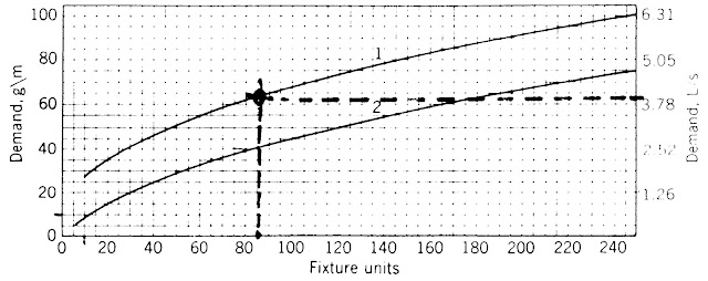
Figure showing Demand Load for flush valves & flush tanks

Figure 1:  Demand Load for predominant (1) flush valves & (2) flush tanks  [source:- Mechanical & Electrical Equipment in Buildings]


Figure showing Flowchart for typical pipes

Figure 2:  Flowchart for typical pipes  [Source:- Mechanical & Electrical Equipment for Buildings]


                      3.            Using total fixture units, determine the demand loadc for the relevant flushing mechanism from figure 1.
c. 3.78 L/s demand, for 85 FU.


                       4.            Using demand load [3], determine an approximate pipe sized from fig. 2 that is closest to the flow velocity of 3 m/s.
d.  40 mm dia. pipe, for 3.8 L/s demand.


                     5.            Using demand load [3] and approx. pipe size [4], determine the pressure loss in the water meter [D] from fig. 3:

                 D         = 62 kPa


Figure showing Pressure losses in Water Meters

Figure 3:  Pressure losses in Water Meters  [Source:- Mechanical & Electrical Equipment in Buildings]


                    6.            Calculate the maximum frictional loss [C] that can be tolerated in the service pipe:

                 C         = E - (A + B+ D)
                 = 350 - (103 + 100 + 62)      = 350 - 265
                = 85 kPa


                    7.            Calculate the Pipe length equivalent of fittings
                 [DL'] (estimated at 20 % of DL):
                 DL'      = 0.2 x DL = 6 m


                    8.            Calculate the total equivalent length (TEL) of the piping:

                TEL      = DL + DL'    = 30 + 6          = 36 m


                    9.            Calculate the unit-frictional loss of the pipe:

                 100 x C/TEL              = 100 x 85/36            = 189 kPa


              10.         Using the demand load [3] and the unit frictional loss [9], determine the pipe sizee from fig. 2
e.  50 mm dia. service pipe size


Table showing Maximum allowable pipe sizes


Table 4:  Maximum allowable pipe sizes  [Source:-  National Building Code of Jamaica 1983]

24 August 2011

Domestic Hot Water Systems: Heat Sources, Methods, Systems, & Distribution


PAUL HAY Capital Projects


Hot Water Systems

Author:            Paul Hay
e-mail:              paul.hay@phcjam.com
profile:             www.linkedin.com/in/phcjam

1.0       INTRODUCTION TO HOT WATER SYSTEMS

1.1       Domestic Hot Water (DHW) is needed for comfort and a degree of sterilization particularly in Laundries and Kitchens.

1.2       In Jamaica, the need for hot water is greatest in hotels, hospitals, pharmaceutical manufacturing and food processing facilities.

1.3       DHW Systems vary depending on (a) heat source, (b) Method of heating water, (c) local versus central equipment and (d) respective distribution trees.

2.0       HEAT SOURCES

2.1       Solar Energy is the only renewable source of energy used.


2.2       Natural gas and electricity are also used as energy sources.

2.3       Otherwise, heat-recovery devises can be used to heat water.

3.0       METHODS OF HEATING

3.1       Water is heated to a maximum temperature of 60 deg. C.

3.2       On-demand heaters do not use no storage tanks:
            3.2.1   Heaters rapidly heat water to the desired temperature and immediately distributes it;
            3.2.2   Heater capacity is equivalent to the peak demand.

3.3       Storage tanks hold approximately one-third the daily cold water consumption:
            3.3.1   A pressure-relief valve is placed on storage tanks as a safeguard against excess temperature and pressure.
            3.3.2   Direct heating involves (a) the use of submersible electrical heating elements, or (b) water is first passed through coils which are subsequently heated by solar radiation, fire, or hot gases;
         3.3.3   Indirect heating involves (a) the use of heat-extracting devices, such as incinerators, not primarily meant to heat water, or (b) passing steam or hot liquids through submerged heating coils.


.


Figure 1: Recommended Capacity of Hot Water Tanks [source:- Journal of Light Construction Field Guide (vol. 2)]


4.0       LOCAL & CENTRAL SYSTEMS

4.1       Local systems are recommended where distance between areas of use exceed 15 m;

4.2       Central systems should be located nearest to fixtures which utilize the most hot water (eg. dish-washers and washing machines.)


Figure 2: Central Hot Water Distribution [source:- Journal of Light Construction Field Guide (vol. 2)]

5.0       DISTRIBUTION TREES

5.1       EEBC-94 requires all exposed piping and storage tanks to be insulated.

5.2       A check valve is located on the cold water intake pipe to prevent hot water entering the cold water distribution tree.

5.3       If hot water storage tanks are located indoors, the pressure relief valve should be connected to a drain.
5.4       A non-circulating system has a distribution tree directly from the heater to individual plumbing fixtures.

5.5       A circulating system has a return line to the heater:
            5.5.1   This system is used in large residences or systems;
            5.5.2   Time for delivery of hot water to fixtures is reduced;
            5.5.3   A circulating pump can be used for constant supply of hot water.

6.0       INSTALLATION

6.1       Gas-burning equipment should be installed in well ventilated areas.

6.2       Exposed open-flame equipment should not be installed in bedrooms, enclosed garages, or rooms primarily intended for storage.

6.3       Where more than one fixture is supplied by a single gas line, each fixture shall receive an independent lock-off valve.

6.4       Equipment should be accessible for servicing and repair.

_________________________________________________


FURTHER READING

Mechanical and Electrical Equipment for Buildings, Benjamin Stein & John S. Reynolds, John Wiley & Sons Inc., U.S.A.
Construction Materials & Processes, Don G. Watson, McGraw-Hill Book Co., USA.
                        Jamaica Energy Efficiency Building Code [EEBC-94], Jamaica Bureau of Standards

18 August 2011

Water Distribution: pumping systems, pipes, fittings & valves


PAUL HAY Capital Projects


Subject:         Water Distribution
Author:          Paul Hay
e-mail:            paul.hay@phcjam.com
profile:           www.linkedin.com/in/phcjam


1.0       INTRODUCTION   

1.1       An adequate supply of potable water shall be provided to each plumbing fixture;

1.2       Water shall be distributed in a manner that ensures it is kept clean and sanitary;

1.3       Good design requires sufficient fittings and valves for ease of maintenance; and

1.4       There should be minimum interference with the architectural form.


2.0 DISTRIBUTION SYSTEMS

2.1       Up-feed distribution involves the distribution of water under the pressure available at the water main or from pressure tanks fed by pumped wells:
            2.1.1   Up-feed systems are primarily used in low-rise buildings;
            2.1.2   Water pressure available at the main must be greater than 103 kPa (15 psi);
            2.1.3   Otherwise, pressure available at main shall exceed losses due to (a) flow through meter, (b) fiction in piping, and (c) height of water column in order to provide proper flow pressure to the highest fixture.


Figure 1: Upfeed Distribution System [source:- Journal of Light Construction Field Guide (vol. 2)]


2.2       Pumped Up-feed Distribution utilizes pumps to supply the additional pressure required:
            2.2.1   Water must first be collected in low-level storage tanks (because direct connection of pumps to the water main is illegal in Jamaica);
            2.2.2   Pumped up-feed systems are primarily used in medium-rise buildings;
            2.2.3   Back-up generators must be provided to allow distribution of water during a power outage.

2.3       Down-feed distribution involves the pumping of water to upper level storage tanks which gravity feed to plumbing fixtures:
            2.3.1   Static Pressure is the pressure exerted by a column of water by virtue of its depth below its stationary head;
            2.3.2   Tanks shall be elevated in order to provide the static pressure needed on the floor immediately below;
            2.3.3   With insufficient head, tanks can be pneumatically charged with an air compressor to attain the required pressure:
                        2.3.3.1            Air-charged pneumatic pumping systems result in greater levels of dissolved air which may result in an undesirable “fizz” on discharge;
                        2.3.3.2            Dissolved oxygen increases corrosiveness of the water supply.
            2.3.4   Water distribution for high-rise buildings should be divided into zones up to 45 m (150 ft.) high:
              2.3.4.1          Static pressure beyond this height can damage plumbing fixtures;
              2.3.4.2            Each zone must be served by independent distribution systems and plumbing.


3.0       PIPES & FITTINGS
3.1    Water supply pipes and fittings can be brass, cast iron, malleable iron, galvanized wrought-iron, galvanized steel, or several types of plastic:
            3.1.1   Copper does not corrode and is durable:
                      3.1.1.1            Copper is subject to electrolytic attack if connected to a dissimilar metal without dielectric separation;
            3.1.1.2            Fittings can be (a) by flared compression joint,  (b) solder-type or brazing fittings;
                        3.1.1.3            Copper’s smooth interior permits the use of smaller sized pipes; and
                        3.1.1.4            Copper pipe should not be used for hot water systems where temperature exceeds 60EC (140E F).
            3.1.2   Galvanized Steel has a long service life:
                        3.1.2.1            Galvanized pipes are dimensionally stable and strong;
                        3.1.2.2            Pipes used in water distribution are joined with screwed fittings;
                        3.1.2.3            Pipes may be used for both cold and hot water distribution, and
                        3.1.2.4            Water Treatment may be required against corrosiveness of water.
         3.1.3   Rigid Plastic Pipe is light-weight offering exceptional resistance to (a) chemicals, (b) impact, and (c) pressure:
                        3.1.3.1            Rates of expansion exceed those of copper and steel;
                        3.1.3.2            Special adapters are available for joints with metal pipes;
                        3.1.3.3            Fittings are typically solvent-welded to the pipes;
                        3.1.3.4            Polyvinyl Chloride (P.V.C.) is one of the common types;
                        3.1.3.5            Polyvinyl Dichloride (P.V.D.C.) Should be used to carry hot water no hotter than 82E C (180E F).

3.2       Except for valves and similar devices, fittings used must be the same material as the pipe;

3.3       Pumps shall be connected with unions;

3.4       Cross connection is an arrangement of piping or connections that allows contamination:
            3.4.1   Syphoning of contaminants occurs when there is a difference in pressure, or a vacuum, in the water distribution system;
            3.4.2   Air gap or Air break is the vertical separation between a pipe or faucet and the flood-level rim of the receptacle;
            3.4.3   Back flow or Check valves allow water to flow in only one direction.


Figure 2: Drainpipe Fittings [source:- Journal of Light Construction Field Guide (vol. 2)]


4.0       VALVES & CONTROLS

4.1       Pressure Regulators should be used in cases when (a) water pressure in mains is excessive, and (b) with problems of variable pressure at different floor levels;

4.2       Valves shall be used (a) on each riser, (b) on each branch to bathrooms, kitchens, etc. and (c)  run-outs to individual fixtures.

_________________________________________________


FURTHER READING

Mechanical and Electrical Equipment for Buildings, Benjamin Stein & John S. Reynolds, John Wiley & Sons Inc., U.S.A.
Construction Materials & Processes, Don G. Watson, McGraw-Hill Book Co., USA.
  

03 August 2011

Water Treatment - Softening, Odor Removal, Sediment Removal & Disinfection


PAUL HAY Capital Projects
  

Water Treatment

Author:          Paul Hay
e-mail:            paul.hay@phcjam.com
profile:           www.linkedin.com/in/phcjam


1.0       INTRODUCTION TO WATER TREATMENT            


1.1            Precipitation typically has few impurities, almost no bacterial content, and minimal amounts of minerals and gases;

1.2      Precipitation may be contaminated with physical pollutants from the catching surfaces;

1.3      Ground water is susceptible to chemical alteration in percolation;

1.4     Potable water may be obtained from aquifers, surface run-off or through desalination (which is generally expensive); 
           1.4.1       Potable water is generally obtained from public water supply systems.
        1.4.2    Where available, public water supply systems are adequately monitored to provide a dependable safe source of water.
           1.4.3       Water taken from other sources should be carefully analyzed and treated before use.


1.5      90% of pathogens die naturally after storage over a 5 - 7 day period; and

1.6       Treatment processes range from sedimentation to distillation.


2.0       PUBLIC WATER SUPPLY MAY NEED SOFTENING     


2.1      Water treatment of the public water supply may only be needed in the event of unacceptable hardness:
            2.1.1   Hard water has over 58.6 ppm of Calcium and magnesium salts;
         2.1.2   Water softeners are the most common means of removing these salts from domestic water supply.

2.2       Water softeners are not always cost effective:
            2.2.1   They require additional expenditure on equipment, chemicals, and labour;
            2.2.2   Water is also more corrosive after softening.   

2.3       Operating costs are lower and require less equipment when used primarily for treatment of the hot water supply.


3.0       GROUND WATER MAY NEED ODOR REMOVAL


3.1       Ground water is usually clean but softening and odor removal is important;

3.2       Aeration can (a) remove odors due to hydrogen sulfide and algae, (b) improve taste and colour of water, and (c) oxidizes iron and manganese, so that they may be removed by filtration:
            3.2.1   Aeration is achieved in tanks by passing water through a series of perforated plates in streams or droplets;
         3.2.2   Otherwise, aeration is achieved by maximizing the exposure of water to air (e.g. waterfalls, fountains, etc.).

3.3       Activated carbon filters remove tastes and odors by extracting dissolved gases, soluble organic material and fine solids.


4.0        SURFACE WATER MAY NEED SEDIMENT REMOVAL & DISINFECTION


4.1       Surface water is likely to be contaminated and should be treated by (a) sedimentation, (b) coagulation, (c) disinfection and (d) filtration;

4.2       Sedimentation is the process by which heavy  suspended particles settle in inactive water conditions:
           4.2.1   A minimum of two tanks should be used each with 24-hours storage capacity to allow de-silting operations without affecting distribution of water; and,
            4.2.2   baffles can be used to slow the flow of water.

4.3       Coagulation (Flocculation) removes colouration and suspended matter:
            4.3.1   Particles combine with alum (hydrated aluminium sulfate) in slow moving water to form floc;
            4.3.2   Heavy particles settle in a process similar to sedimentation, and some adjustment of pH may be required in the process.

4.4       Chlorine has become the standard means of disinfection:
            4.4.1   This process should be applied first where iron and manganese concentration is a problem, as these adversely affects plumbing and other methods of water treatment;
            4.4.2   Hypo-chlorinators automatically add chlorine solution to water;
            4.4.3   Effective disinfection requires (a) a minimum concentration of 4mg/L of chlorine in water for at
                       least 30 minutes, (b) lower pH; and (c) high concentrations should be used for faster
                       disinfection.


4.5       Filtration can remove (a) suspended particles, (b) some bacteria, (c) colour and (d) taste:
          4.5.1   Chlorination/fine filtration oxidizes iron and/or manganese to form precipitate that is removed by the fine filter; and
            4.5.2   Chlorination/fine filtration kills iron bacteria and disinfects.

_________________________________________________


FURTHER READING

Mechanical and Electrical Equipment for Buildings, Benjamin Stein & John S. Reynolds, John Wiley & Sons Inc., U.S.A.
Construction Materials & Processes, Don G. Watson, McGraw-Hill Book Co., USA.

Water Quality - Physical, Biological, Chemical & Radiological Characteristics


PAUL HAY Capital Projects


Topic:            Water Quality
Author:          Paul Hay
e-mail:            paul.hay@phcjam.com
profile:           www.linkedin.com/in/phcjam


1.0       INTRODUCTION           


1.1            Precipitation typically has few impurities, almost no bacterial content, and minimal amounts of minerals and gases;

1.2       Pollutants affect the physical, biological, chemical and radiological characteristics of water:
            1.2.1   Precipitation may be contaminated with physical pollutants from the catching surfaces;
            1.2.2   Ground water is susceptible to chemical alteration in percolation;

1.3       The designer’s task is to specify water quality appropriate to its task; but

1.4       Reliability and dependability should be primary concerns in the choice of potable water supply (i.e. cost is secondary).


2.0       PHYSICAL CHARACTERISTICS

2.1       Turbidity is visible and therefore undesirable:
            2.1.1   Turbidity is the  result of suspended particles which can be either (a) inorganic, as clay, silt, etc., or (b) organic, as plankton;
            2.2.2   Health may not be adversely affected.

2.2       Colour is similarly undesirable because of its visibility:
            2.2.1   Colour results from micro-organisms or dissolved materials that can be (a) inorganic, as iron, or (b) organic, as decayed vegetation;
            2.2.2   Health may not be adversely affected.

2.3       Taste and Odor results from (a) inorganic salts, (b) dissolved gases and (c) organic compounds.

2.4       Water is generally preferred at temperature ranges between 10 deg. C and 16 deg. C.

2.5       Foamability usually indicates concentration of detergents:
            2.5.1   Drinking water should be promptly investigated;
            2.5.2   Foaming may indicate dangerous pollutants associated with domestic waste;
            2.5.3   Modern detergents are not bio-degradable under anaerobic conditions as exists in some septic-tank drainage fields.


3.0       BIOLOGICAL CHARACTERISTICS

3.1       Biological contamination results from disease-producing organisms as (a) bacteria, (b) protozoa, and (c) viruses.

3.2       Organisms and by-products are readily destroyed at treatment plants:
            3.2.1   Biological water tests are complex and time consuming;
            3.2.2   The coliform group of bacteria (a) outnumbers other disease-producing organisms in water; and (b) is always present in fecal wastes of humans, many animals and birds.

3.3       Human settlement should be kept away from water-sheds.

3.4       Water should be stored in the dark at low temperatures.


4.0       CHEMICAL CHARACTERISTICS

4.1       pH value is the measure of (a) hydrogen ion concentration in water, as well as (b) acidity and (c) alkalinity:
            4.1.1   pH value is initially tested to determine the need for (a) corrosion control, (b) disinfection, and (c) chemical doses;
            4.1.2   In nature, the pH values of water can range between 0 and 14:
                        4.1.2.1 A pH value of 7 is neutral;
                        4.1.2.2 pH values lower than 7 indicates (a) acidity and (b) corrosiveness;
                        4.1.2.3 pH higher than 7 indicates alkalinity.

4.2       Alkalinity indicates the levels of bicarbonate, carbonate or hydroxide components.

4.3       Hardness indicates the level of calcium and magnesium salts:
            4.3.1   “Hard” water (a) inhibits cleaning action of detergents and (b) deposits scale on hot-water pipes and cooking utensils, as kettles;
            4.3.2   Temporary hardness is removed when water is heated; but not permanent hardness.

4.4       Toxic chemicals include: arsenic, barium, cadmium, chromium, cyanides, fluoride, lead, selenium, and silver.

4.5       Other chemicals of concern are: chlorides, copper, iron, manganese, nitrates, pesticides, sodium sulfates, and zinc.


5.0       RADIOLOGICAL CHARACTERISTICS: Radiological contamination results from the mining and the use of radio-active materials.


_________________________________________________


FURTHER READING

Mechanical and Electrical Equipment for Buildings, Benjamin Stein & John S. Reynolds, John Wiley & Sons Inc., U.S.A.
Construction Materials & Processes, Don G. Watson, McGraw-Hill Book Co., USA.