ShareThis Widget

04 July 2011

Electric Lighting: Lamps, Efficacy, Mounting, Effects on Cooling Load & Calculation of Fixtures needed


PAUL HAY Capital Projects


Electric Lighting

Author:          Paul Hay
e-mail:            paul.hay@phcjam.com
profile:           www.linkedin.com/in/phcjam


1.0     1.0     SPECTRAL PROPERTIES OF LAMPS VARY

1.1       Chromaticity, Colour Temperature or Correlated Colour Temperature (CCT) indicates the apparent colour of light emitted from a lamp:
            1.1.1   Incandescent lamps emit "warm" reddish-white light [CCT = 2,700K];
            1.1.2   Some fluorescent lamps emit "neutral" white light [CCT = 3,500K];
            1.1.3   Other fluorescent lamps is a "cool" bluish-white [CCT = 4,100K].

1.2       Colour Rendering Index (CRI) indicates the ability of a light source to accurately represent the colour of an object [0 < CRI <100]:
1.2.1   CRI = 0 indicates a light source without colour (eg. black and white television);
            1.2.2   Good colour rendering exists when 70 < CRI < 80.

1.3       High Intensity Discharge (HID) lamps include Mercury Vapour (MV), Metal Halide (MH), and High Pressure Sodium (HPS):
1.3.1   Mercury Vapour lamps emit a bluish-white light:
1.3.1.1            Colour rendition is generally worse than fluorescent lighting;
1.3.1.2            It is used outdoors because of its low cost and long life.
1.3.2   Metal Halide lamps can have twice the efficacy of MV lamps:
1.3.2.1            They have good colour rendition; but
1.3.2.2            They are expensive and have a shorter life than MV lamps.
1.3.3   High Pressure Sodium lamps emit yellowish light:
1.3.3.1            They have poor colour rendition, and
1.3.3.2            They are used to illuminate streets and parking lots.


2.0    LUMINAIRE EFFICIENCY VARIES            

2.1       Luminaire type refers to the construction of the light fixture: bulbs enclosed, ballasts, volume of the casing, materials used and ventilation conditions.

2.2       The efficiency with which a light source converts electricity to light is called efficacy.

2.3       The efficacy of different types of luminaires vary from low to high are as follows:  Incandescent [8 - 20 lm/W], Mercury Vapour [30 - 60 lm/W], Fluorescent [32 - 102 lm/W], Metal Halide [70 - 100 lm/W], High-pressure Sodium [50 - 130 lm/W], ballast losses being included for all but incandescent luminaires.

2.4       Incandescent lamps emit a reddish-yellow light.

2.5       Incandescent lamps with higher efficacies generally have special reflectors designated as follows: "R" - reflector, "PAR" - parabolic aluminized reflector, "ER" - elliptical reflector.

2.6       Fluorescent lamps last 20 times longer than incandescent lamps but are more expensive.


3.0  ELECTRIC LIGHTING IS TRANSFORMED INTO HEAT


3.1       All electrical power used to produce light is eventually converted into heat:
3.1.1   In many instances, electric lighting is the most significant contributor to a room=s cooling load;
3.1.2   Where fixtures are recessed into ceilings, cooling loads increase by two means:
2.1.2.1            Electric light directly heats the room enclosure; and
2.1.2.2            Heat passed into ceiling space is extracted by the return air.
3.1.3   In multi-storey buildings, all heat produced by electric lighting increases the building's cooling load, if lights are on long enough.

3.2       There are instances when heat produced by electric lighting does not contribute to a room=s cooling load:
3.2.1   If air-returns are ducted through the ceiling space;   
3.2.2   When air-conditioning systems do not run continuously; and
3.2.3   In rooms adjacent to unconditioned spaces.

3.3       Convective components become instantaneous cooling loads.

3.4       Radiative components contribute to cooling loads at a later time:
3.4.1   Building structure stores the radiative component, which only becomes a cooling load when surface temperatures exceed the air temperature:
3.4.1.1            Materials with greater heat capacities produce longer delays;
3.4.1.2            Increasing thickness of materials increase their heat capacities.
3.4.2   Furniture and floor finishes can reduce thermal storage within rooms:
3.4.2.1            Simple heavy-weight furniture without carpets are least effective;
3.4.2.2            Ordinary furniture with carpets are most effective.
3.4.3   Transmission of heat is also a function of the internal surface coefficients and the room's ventilation rate:
3.4.3.1            Carpeting reduces heat transfer from the floor; and
3.4.3.2            Rooms with higher ventilation rates have greater heat transfers.

3.5       Transfer of thermal energy from luminaires (i.e. radiation, convection, and conduction) depends on the type of luminaire, method of mounting, and ceiling construction.


4.0 METHODS OF MOUNTING AFFECT DISTRIBUTION OF HEAT


4.1       Suspended luminaires distribute thermal energy predominantly by convection.

4.2       Recessed luminaires distribute thermal energy as suspended luminaires.

4.3       Surface-mounted luminaires have greater conduction of thermal energy.


5.0 CEILING CONSTRUCTION AFFECTS COOLING LOADS

      
5.1       Heat passing into ceiling spaces can either enter room enclosures through cracks between suspended ceiling tiles and framing:
5.1.1   If ceiling space is used as a plenum, recessed luminaires transfer heat as if the luminaires were suspended without a ceiling;
5.1.2   Where return-air is ducted, heat from the ceiling space is convected into the conditioned space and increases the cooling load.

5.2       Heat passing into ceiling without gaps do not contribute to cooling load if return-air is ducted.


6.0 QUANTITY OF LUMINAIRES HAVE TO BE CALCULATED


6.1       The quantity of luminaires required can be calculated using the Lumen method as follows:

No. Luminaires =     Desired Illumination (lux) x Room Area (m2 )                     [6.1]
M x UF x LLF x Lamps/luminaire x lm/lamp
where,
M =      Multiplier (as per manufacturer=s specifications)
UF =   Utilization Factor (as per manufacturer=s specifications)
LLF =  Light-Loss Factor

6.2       Utilization Factor (UF) is the ratio of Luminous Flux on a reference surface to the total flux of the installation:
6.2.1   UF can be found in manufacturer=s photometric tables or Lighting Handbook of Illumination Engineering Society (IES);
6.2.2   UF depends on (a) room geometry, (b) reflectivity of surfaces, and (c) photometric characteristics of the luminaires; and
6.2.3   Room Cavity Ratio (RCR) is a lumped parameter used to express the room characteristics:

RCR  =           5h x [L + W]/[(L x W)]                                                                [6.2]

where,
L =       Length of room (m)
W =     Width of room (m)
h =      Mounting height above a reference plane (approx. 0.85 m above the finished floor level)
                                    h =      H - e - p          [6.3]


where,
H =      Height of room (m)
e =       Height of reference plane above floor (m)
p =       Distance Luminaire is suspended from ceiling (m)

6.3       Light Loss Factor (LLF) is the ratio of mean luminous flux from a lamp to its rated output, after aging of the lamp, accumulation of dirt luminaire and room surfaces, and other contributing loss factors.

Figure showing light dirt-depreciation on luminaires

Figure 1: Light Dirt Depreciation


6.4     The ratio of the minimum to mean illumination on a task area should equal or exceed 0.8:
6.4.1   This is normally achieved within the central region if the ratio of the minimum to maximum direct illuminance is greater than 0.7;
6.4.2   The maximum spacing-to-height ratio (SHR MAX) is defined for a square arrangement of luminaires which satisfies condition 5.5.1 as follows:

                        S MAX =        SHR MAX x h                                                                            [6.4]

where,
S MAX =        Maximum spacing between rows of luminaires


7.0  CALCULATION OF REQUIRED LUMINAIRES


Example 7.1

Calculate required quantity of luminaires given the following:-

Room dimensions (W x L x H), m =  2.5 x 4.0 x 2.5
Reflectances (Clg. & Wall)            =  0.7 & 0.5
Desired Illumination =  500 lux
Lamp/Luminaire      =  2 No.
Lumen/Lampa          =  2,800 lm

            RCR   =  5 h [L + W]/[L x W)]                                                                                   [6.2]
=  5(2.5 - 0.85)[4.0 +2.5]/[4.0 x 2.5]
=  5 x 1.65 x 6.5/10 =  5.36

            Using RCR = 6,

            UFb     =  0.41

No. of Luminaires    =      Desired Illumination x Room Area                           [6.1]
                          M x UF x LLF x Lamp/Lumin. x Lumen/Lamp

                        =         500 x (2.5 x 4)        
                           1.0 x 0.41 x 0.85 x 2.0 x 2800

                        =   5000          =  2.562          (use 3 No.)
                                       1951.6

            Smax      =  h x SHRmax
            =  1.65 x 1.6               =  2.64 m


a.         Value of Lumen/Lamp complies with Phillips F40T12/CW/IS lamp;

b.         UF is manufacturer's specifications for 2 lamp strip luminaire & listed surface reflectances.


Figure showing Utilization Factors for a specific luminaire

Figure 2: Utilization Factors


FURTHER READING

Construction Materials & Processes, Don G. Watson, McGrawHill Book Co., USA, 1978;
            Lighting Handbook, Philips Lighting Company, USA, 1984


01 July 2011

Waste Disposal: Design & Connection of Plumbing Fixtures


PAUL HAY Capital Projects


Waste Disposal: Design & Connection of Plumbing

Author:          Paul Hay
e-mail:             paul.hay@phcjam.com
profile:            www.linkedin.com/in/phcjam


1.0        DRAINAGE SYSTEMS NEED TO BE DESIGNED

1.1_          Each plumbing fixture provided with water supply must be drained.

1.2       Waste must be safely disposed of to prevent contamination.
1.2.1    Ventilation of the drainage system must be considered.
1.2.2    Gases must not be permitted to enter the building.
1.2.3    A disposal system must be chosen to suit the waste generated;
1.2.4    Disposal must not be close to sources of water; and 
1.2.5    Maintenance and inspection must be facilitated.

1.3       Recycling and the matching of water quality to usage can reduce the dependence on potable water and reduce drainage loads.


Figure showing Residential Drainage System


Figure 1:  Residential Drainage System  [Source:- AIA Architectural Graphic Standards, 1981]


2.0        FIXTURES MUST CONNECT TO A DISPOSAL SYSTEM

2.1       A waste fixture is a fixture designed for disposal of waste without assistance from flushing mechanisms.
2.1.1        Waste pipes connect waste fixtures to the drainage system.
2.1.2    A trap is a device which prevents the exhaust of drainage gases into the building.
                        2.1.2.1 Each plumbing fixture should have a trap.
2.1.2.2             Traps are generally located less than 600 mm from a fixture.
2.1.2.3             Water evaporates from traps that are infrequently used: floor drains being especially vulnerable to such occurrence.

Table showing Minimum trap sizes for plumbing fixtures

Table 1:  Minimum trap sizes for plumbing fixtures  [Source:- National Building Code of Jamaica, 1983]

2.1.3    Trap ventilating pipe is a pipe connected to the outlet end of a trap terminating in an open end.
2.1.3.1             It prevents the water seal in the trap from being lost.
2.1.3.2             Vents are also necessary to allow fresh air entry into drainage systems and to exhaust gases already in the system.
            2.1.4    Trapped gully basins are open chambers that receive outflow from waste pipes.
2.1.5    Grease or interceptor trap is a device that prevents grease, petroleum products or other undesirable waste products from entering drains.

Table showing Minimum sizes for trap ventilating pipes

Table 2:  Minimum sizes for trap ventilating pipes  [Source:- National Building Code of Jamaica, 1983]


2.2       A soil fixture is a fixture designed for flush-assisted disposal of waste matter.
.                       2.2.1    Soil fixtures generally have built-in traps.
2.2.2    Soil pipes connect soil fixtures to a manhole
2.2.3    A manhole is an enclosed chamber that permits inspection and maintenance.
2.2.3.1             Manholes shall be no further than 50 m from the next manhole, or 15 m from a septic tank or other disposal system.
2.2.3.2             Where a manhole is located indoors, it shall be fitted with gas and water-tight cover.
2.2.4    A backdrop manhole is a manhole against which a vertical shaft has been constructed, on the side of the incoming drain, terminating in an easy bend before  entering the manhole.
2.2.4.1             It is used where there is an elevation difference between the inlet and outlet of a manhole in excess of 300 mm.
2.2.4.2             Access shall be provided to the vertical shaft to facilitate inspection and maintenance.

Table showing Drainage Fixture Units
Table 3:  Drainage Fixture Units [Source:- JLC Field Guide to Residential Construction]


Table showing Stack and drain pipes sizes


Table 4:  Stack and drain pipes sizes [Source:- National Building Code of Jamaica, 1983]


2.3       A branch pipe is a pipe connecting plumbing fixtures to a vertical stack.
2.3.1    Vertical stack is a vertical pipe terminating in a manhole or trapped gully basin.
2.3.2    A one-pipe system receives discharge from both waste and soil fixtures providing both traps are ventilated.
2.3.3    A two-pipe system separates discharge from waste and soil fixtures.
2.3.3.1             A vertical stack for waste fixtures terminates over a trapped gully basin.
1.3.3.2             A vertical stack for soil fixtures and one-pipe systems terminates in a manhole.
2.3.4    A branch drain connects a vertical stack or trapped gully basin to manhole.

2.4       A drain ventilating pipe is a pipe used to ventilate a drainage system: it connects to a manhole or branch drain at one end and terminates in an open end above the roof eaves.

2.5       A main drain is a pipe connecting manholes together or a manhole to a disposal system.

Table showing Maximum gradients for drain-pipes

Table 5:  Maximum gradients for drain-pipes  [Source:- National Building Code of Jamaica, 1983]


FURTHER READING

National Building Code of Jamaica ,2nd edition, Ministry of Finance & Planning, Ja., 1992.
Mechanical and Electrical Equipment for Buildings, 8th edition, Benjamin Stein, John S. Reynolds, John Wiley & Sons Inc., USA, 1992;
Construction Materials & Processes, Don G. Watson, McGrawHill Book Co., USA, 1978;
Ramsey/Sleeper Architectural Graphic Standards, A.I.A., Robert T. Packard (ed), John Wiley & Sons Inc., USA, 1981

30 June 2011

Principles of Lighting: Visible Light, Perception, Light source, & Illumination


PAUL HAY Capital Projects


Principles of Lighting

Author: Paul Hay
e-mail:   paul.hay@phcjam.com


1.0     INTRODUCTION TO LIGHT


1.1               1.1              Light is an electro-magnetic wave.

Figure showing Visible light as a portion of the Electromagnetic Spectrum

Figure 1: Visible light as a portion of the Electromagnetic Spectrum. Source: Philips Lighting - Lighting Handbook


1.2       The electro-magnetic spectrum for light has wave-lengths in the range 0.2 – 1,000 µm:
1.2.1    Solar radiation has a spectrum with wave-lengths in the range 0.3 – 25 µm; and
1.2.2 Visible light has a spectrum with wave-lengths in the range 0.38 – 0.78 µm.
Figure showing how sensitivity of the human eye to colours varies

Figure 2: Sensitivity of the human eye to colours varies.  Source:- Philips Lighting - Lighting Handbook


1.3       Objects are perceived from a complex pattern of light, shade and contours.

1.4       Light from at least two directions, preferably at an acute angle to each other, provides the best modeling characteristics for display of three dimensional objects.
Figure showing how (a) Diffuse lighting destroys textures, but (b) necessary modeling shadows are created when combined with directional lighting.

Figure 3: (a) Diffuse lighting destroys textures, but (b) necessary modeling shadows are created when combined with directional lighting.  Source:- Mechanical & Electrical Equipment for Buildings


1.5       The ability of the human eye to distinguish details depends on (a) the size of the object being viewed, (b) contrast of the object with its immediate surroundings, and (c) the level of illumination present.


2.0      CHARACTERISTICS OF LIGHTING SOURCES

2.1       Luminous Flux is the radiant energy which produces a luminous sensation [i.e. lumens].

2.2       Luminous Efficacy is the ratio of total luminous flux emitted by a light source to the total power input [i.e. Lumens/Watt]:
            2.2.1    The Luminous Efficacy of daylight varies between 100 – 120 lumens/Watt; and
            2.2.2   Current electric-lighting systems attain efficacies between 60 -90 Lumens/Watt.

3.0      PRINCIPLES OF ILLUMINATION

3.1.      Wave intensity [I] is the power of radiant flux incident on a unit area of a reference plane perpendicular to the direction of propagation [i.e. W/m2].

3.2       Illumination is the density of luminous flux incident on a unit area of a reference plane [i.e. lux]:
            3.2.1.   The Inverse-square Law states that wave intensity [I] from a point source in free space is inversely proportional to the square of the distance (d) from the source:

                        I α 1/d 2                                                                                                           3.1

            3.2.2. The Cosine Law states that radiant flux [F] on any surface varies as the cosine of the angle of incidence (q) of the wave to the normal of the surface:

                        F α Cos q                                                                                                        3.2

3.3       Luminous flux from the sky gives relatively constant illumination, but varies according to the portion of sky which is incident on the surface being evaluated:
            3.3.1.   In the arid tropics, skies are typically isotropic: luminous flux is evenly distributed about the sky, but bright areas exist at (a) the point which mirrors the location of the sun, and (b) the horizon, which is called circumsolar radiation;
            3.3.2.  In the humid tropics, skies are anisotropic: the brightest areas being associated with the location of clouds in the sky.

3.4       Radiant exchange between the sky and a small surface near ground can be modeled by representing the sky as a hemisphere.

3.5       Efficient interior lighting depends on (a) available luminous flux, (b) its distribution, (c) glazing/controller properties and (d) room characteristics. 


27 June 2011

Daylighting: benefits, illumination, & solar control


PAUL HAY Capital Projects


Daylighting: Benefits, Illumination & Solar Control

Author:          Paul Hay
e-mail:            paul.hay@phcjam.com
profile:           www.linkedin.com/in/phcjam


1.0  BENEFITS OF DAYLIGHTING

1.1        Total energy-use in buildings can be reduced by up to 20% in climates like Jamaica's.
1.1.1     Use of electric lights can be reduced by 65%; and
1.1.2     Peak cooling-load can be reduced by 15%.

1.2        The value of buildings are increased; and

1.3        Productivity of occupants is increased.

2.0  PROVIDE ADEQUATE ILLUMINATION

2.1        Illumination required within a room depends on the use of the space.

2.2        Partly cloudy skies are typical of tropical climates and available illumination is generally higher than in locations of higher latitude.

2.3.       Daylight Factors [DF] are used instead of absolute values of illumina­tion, because daylight is by nature variable;
2.3.1     Daylight Factor is the quotient of indoor illumination [Ein] at a specific point to the outdoor illumination [Eout] measured under an unobstructed sky.

DF =    Ein/Eout x 100 (%)                                                                                        [2.1]

2.3.2     Direct sunlight is generally excluded from the measure­ment of both indoor and outdoor illumination.

2.4        A scale model is required to study the illumination and quality of lighting.
2.4.1     For medium to large enclosures, a scale of 1:25 is recommended.
2.4.2     For small spaces with ceiling heights up to 3 m, a scale of 1:10 is recommended.
2.4.3     The scale of the model should be doubled for qualitative studies, to permit greater attention to construction details and allow sufficient distances for eyes or camera.


Figure showing available daylight Illumination at various Latitudes
Fig. 1:

Available Daylight Illumination at various Latitudes


3.0       AVOID THERMAL DISCOMFORT

3.1        Relatively uniform distribution of daylight factors is recommended:
3.1.1     With side-lighting, illumination near windows are typically 200% higher than illumination to the back of a room; and
3.1.2     With sky-lights, illumination beneath the sky-light may only be 50% higher than the lowest illumination away from the sky-light.

3.2        Increasing window-areas increases solar heat-gains, so window performance should be evaluated by use of the Effective Apertures of each window examined:


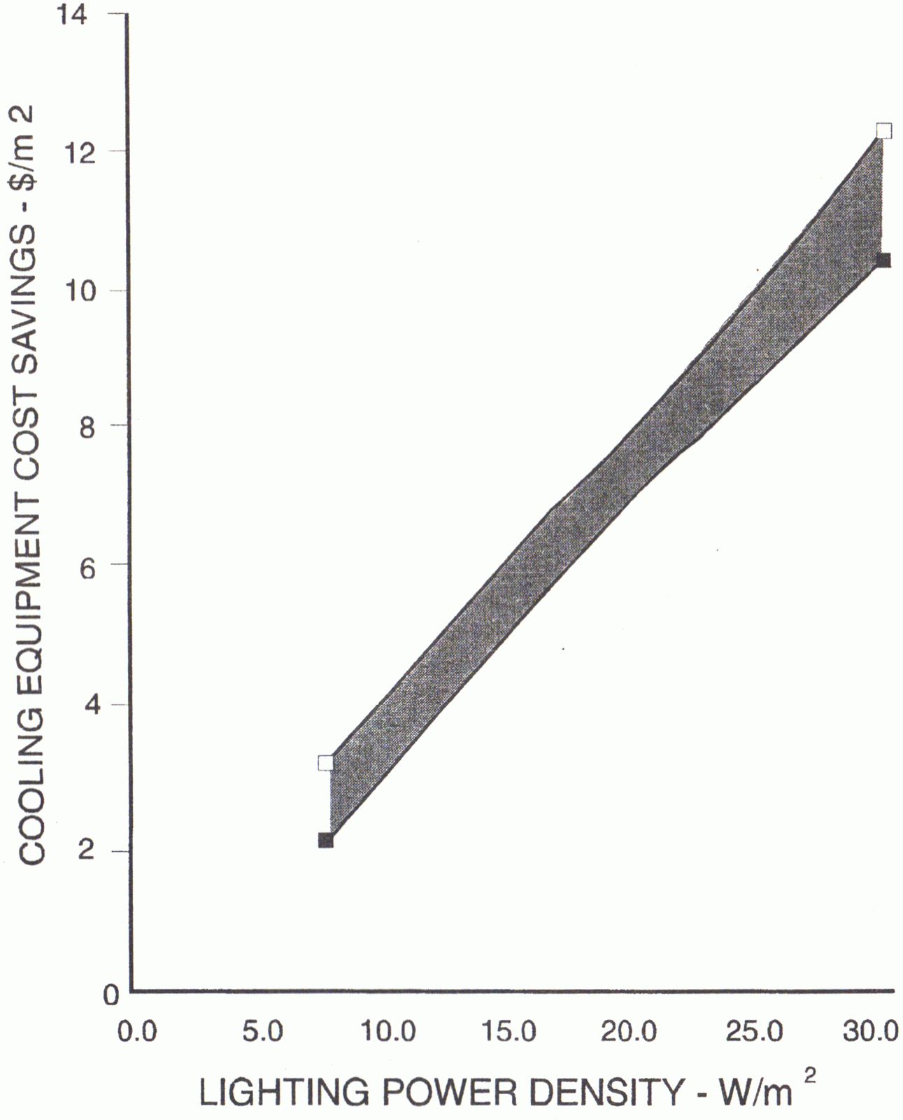
Fifure showing potential cost savings on cooling system with use of daylighting
Fig. 2: Potential Cost Savings on Cooling System with use of daylighting

Table showing Illumination levels for activity/area
Table 1: Illumination levels for activity/area
          
3.2.1     Effective Aperture [EA] is a lumped parameter derived from the window-to-wall ratio of the glazing in ceiling-high walls, or the Skylight-to-roof ratio;           

EA =     WWR x Tv                                                                                      [3.1]

or,        EA =     SSR x Tv x WF                                                                               [3.2]

                        where,
WWR   = Window-to-Wall Ratio [0<WWR<1]
SRR      =  Skylight-to-Roof Ration [0<SRR<1]
Tv         =  Visible transmittance of the glazing
WF       =  Light-well transmission

3.2.2     The ratio of net visible transmittance to Shading Coeffi­cient (i.e. Tv/SC) is typically (a) 0.67 for grey or bronze-tinted glazing, (b) 1.0 for skylight glazing (not considering light-well transmittance), and (c) 1.1 for blue-green glass.

3.3        Daylight Satura­tion is the point at which there is no further reduc­tion in electric-lighting:
3.3.1     For sidelighting, daylight saturation occurs at effective apertures of 0.10 and 0.25,
3.3.2     For sky-lighting, daylight saturation occurs at 0.02 to 0.03.

3.4        If win­dow areas are increased after daylight satura­tion occurs, then solar heat-gains, cooling loads, and overall energy-consump­tion will be increased.

4.0       INTEGRATE ELECTRIC LIGHTING

4.1        Lighting zones must be developed based on contrast levels of daylight illumination:
4.1.1     Lighting zones delineate spaces having similar daylight distribution characteris­tics, but not the nature of lighting required.
4.1.2     Contrast level for a zone is the ratio of maximum to minimum illumination within the zone; and
4.1.3     Three zones are recommended with contrast levels of 1:3, 1:6 and 1:9 respec­tively.
4.1.4     For high windows with a 3 m high ceiling, two daylit zones can assumed by the 15/30 rule-of-thumb:
4.1.4.1  The first 4.6 m [15-ft] in from the windows is predominantly daylit;
4.1.4.2  The next which ends 9.1 m [30-ft] in from the windows is ambient-lit by daylight and is supplemented by electric-lighting.

4.2        The nature of lighting may vary within a zone and a zone can be established outside of daylighting concerns.
4.2.1     General lighting is the illumination generally required throughout an area;


4.2.2     Background lighting is the illumination within the visual field against which an object is seen; and
4.2.3     Task lighting is illumination specifically for visually-demanding activities.   
          
4.3        Appropriate controls must be provided for electric-lights.

4.4        Electric-light should have colour and direction similar to daylight.


FURTHER READING

Daylighting in Architecture, Benjamin H. Evans, Architectural Record Books, New York, 1981;
Concepts and Practice of Architectural Daylighting Fuller Moore, Van Nostrand Reinhold, New York, 1985;